
Flex Circuit Boards Different From Rigid PCBs
Flex circuits can save space and reduce weight while allowing them to adapt to small or irregularly-shaped spaces, a feature not possible with rigid PCBs. In fact, they eliminate the need for wire harnesses and connectors which could increase assembly costs. Choosing the right flex circuit design for your needs will ensure that you can get the maximum benefit from this technology.
Typically, a flex circuit has the same layer structure as a conventional rigid PCB. However, the substrate is usually made of a flexible polymer instead of fiberglass or metal. The most popular choice is a thermosetting polyimide film, which remains flexible after heating and does not soften or tear. This makes PI the ideal material for a flexible PCB design. However, standard PI does not have good humidity resistance and can tear or swell easily. Upgrading to a higher-quality PI film mitigates this issue.
Conductors are the conductive paths that connect each component on the board, and copper is commonly used as the conductive material for flex circuits. A thin layer of insulator separates conductors and protects them from corrosion or damage. This insulator is often made of epoxy, acrylic, or polyethylene naphthalene.
A stiffener is another important element of a flex circuit board, and it is added to reduce the deformation that occurs during fabrication and assembly. Stiffeners also provide structural integrity to the circuit and help reduce vibrations during operation. The most common stiffeners are thin polyimide films, although they can also be made of carbon fibers and other materials.
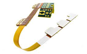
How Are Flex Circuit Boards Different From Rigid PCBs?
The etching process that is applied to a flex circuit is different than the etching process for rigid PCBs. For a flex circuit, the copper foil is annealed by passing it through high-pressure rollers. This elongates the copper’s grain structure, resulting in increased flexibility and improved signal transmission. The annealing process is an integral part of the manufacturing and assembly processes for both rigid and flex PCBs, so it is crucial to ensure that it is performed correctly.
Another difference between flex and rigid circuits is that a flex circuit has less material than a traditional rigid PCB. This can decrease the overall cost of the circuit and make it easier to work with, especially in tight spaces. It also allows the circuit to flex and bend, which is essential for many applications.
There are a variety of types of flex circuits available, but single-sided flex circuits are the most popular. They have one conductive layer on each side of the board and use additional films (usually PI or PET, sometimes flexible solder mask ink) for coverlay. The coverlay insulates the outer surface of the conductors and protects them from corrosion and damage, similar to a protective layer on a rigid PCB.
Creating a flex circuit requires careful consideration of the thickness of the traces and the insulator material. Thicker traces have a lower resistance to bending and can handle greater flexing, while thinner traces are more likely to break if they are bent too sharply. The best solution is to create a design that has both thick and thin traces in order to provide the flexibility needed by your application.


+ There are no comments
Add yours